库包
我们在《OLED显示屏工作原理及示例》一节层讲过,LVGL和U8G2库可用于OLED显示屏的开发。这里也不例外,它们同样可以被用于LCD显示屏的开发。除此之外,我们还经常可以看到在一些小项目中常被使用的、适用于带LCD屏幕嵌入式系统开发的库包,包括Adfruit TFTLCD Library、TFT_eSPI(针对32位MCU。作者主页还提供了一些辅助库包,如可用于Jpeg文件渲染的TJpg_Decoder)以及可以在烧录了MicroPython固件的开发板上使用的st7789_mpy、为树莓派上LCD开发使用的st7789-python(非MicroPython)。
GFX是Graphics的简写。TFT(Thin-Film Transistor,薄膜晶体管)是一种特定类型的LCD(液晶显示,Liquid Crystal Display)技术。作为一种电子元件,它可以精确地控制每个像素的开关状态,从而实现高质量的图像显示。相比于早期的液晶显示技术,TFT液晶显示器具有更好的色彩表现、对比度和响应时间。
ESP32平台、Arduino框架下的TFT_eSPI 开发过程记录
硬件信息:
- 主控模组(ESP32芯片):NodeMCU 32S
- 显示屏(ST7789驱动):1.54寸 240×240 像素 IPS LCD
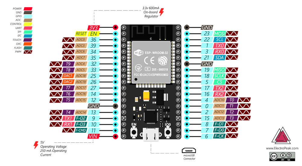
NodeMCU 32S引脚分配信息如下:
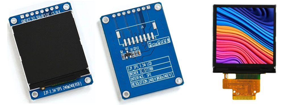
显示屏模块及其裸屏的外观、引脚名称、顺序及功能:
- GND:电源地引脚
- VCC:显示屏主电源供电引脚
- SCL:4线SPI串口时钟引脚
- SDA:4线SPI串口数据输入引脚
- RES:显示屏复位引脚
- DC:数据/命令选择引脚,低电平有效
- CS:片选信号引脚
- BLK:背光控制开关引脚(默认打开背光,低电平时关闭背光)
我习惯使用VSCode配合PlatformIO插件进行开发:
(1)引入TFT_eSPI依赖:
lib_deps =
  TFT_eSPI@^2.5.43
TJpg_Decoder@^1.1.0除了引入TFT_eSPI库外,我还引入了用于显示JPG格式图片的TJpg_Decoder库,他们出自同一位作者Bodmer。
(2)基础配置:
该库有User_Setup.h和 User_Setup_Select.h两个配置文件,分别用于配置具体参数或直接选择已有配置。例如通过User_Setup.h文件配置驱动芯片、主控芯片的引脚;通过User_Setup_Select.h直接配置用于TTGO具体模块的显示驱动。
首先,取消 ST7789 驱动的宏注释:
#define ST7789_DRIVER然后,设置屏幕分辨率。配置文件已为我们准备好TFT_WIDTH、TFT_HEIGHT的可选值,因此也只需要我们注释对应的行即可:
#define TFT_WIDTH  240 // ST7789 240 x 240 and 240 x 320
#define TFT_HEIGHT 240 // ST7789 240 x 240接着,设置芯片引脚,其中的TFT_DC和TFT_RST我没用使用文件默认的值,而是根据我所设计PCB上的引脚分配:
#define TFT_MOSI 23
#define TFT_SCLK 18
#define TFT_DC   12  // 自定义数据/命令引脚
#define TFT_RST 14 // 自定义复位引脚然后,定义需要使用的字体。因为字体会占用单片机闪存和内存空间(存储在 flash,然后通过程序加载至内存),因此最好将冗余字体注释掉。
#define LOAD_GLCD   // Font 1. Original Adafruit 8 pixel font needs ~1820 bytes in FLASH
#define LOAD_FONT2  // Font 2. Small 16 pixel high font, needs ~3534 bytes in FLASH, 96 characters
#define LOAD_FONT4  // Font 4. Medium 26 pixel high font, needs ~5848 bytes in FLASH, 96 characters
#define LOAD_FONT6  // Font 6. Large 48 pixel font, needs ~2666 bytes in FLASH, only characters 1234567890:-.apm
#define LOAD_FONT7  // Font 7. 7 segment 48 pixel font, needs ~2438 bytes in FLASH, only characters 1234567890:-.
#define LOAD_FONT8  // Font 8. Large 75 pixel font needs ~3256 bytes in FLASH, only characters 1234567890:-.
//#define LOAD_FONT8N // Font 8. Alternative to Font 8 above, slightly narrower, so 3 digits fit a 160 pixel TFT
#define LOAD_GFXFF  // FreeFonts. Include access to the 48 Adafruit_GFX free fonts FF1 to FF48 and custom fonts

// Comment out the #define below to stop the SPIFFS filing system and smooth font code being loaded
// this will save ~20kbytes of FLASH
#define SMOOTH_FONT
最后,根据实际情况设置其余选项。例如设置SPI时钟频率:
// #define SPI_FREQUENCY  27000000
#define SPI_FREQUENCY  40000000
// #define SPI_FREQUENCY  55000000 // STM32 SPI1 only (SPI2 maximum is 27MHz)
// #define SPI_FREQUENCY  80000000

// Optional reduced SPI frequency for reading TFT
#define SPI_READ_FREQUENCY  20000000

// The XPT2046 requires a lower SPI clock rate of 2.5MHz so we define that here:
#define SPI_TOUCH_FREQUENCY  2500000
注意到这里我选择的频率是40MHz,这是考虑到使用的是VSPI而不是HSPI。另外上面还有 SPI_READ_FREQUENCY 和 SPI_TOUCH_FREQUENCY 两个频率设置,它们分别是“用于从 TFT 显示屏读取数据时的 SPI 通信频率”以及“用于 XPT2046 触摸屏控制器的 SPI 通信频率”。其实这两个配置在次吃试验中是用不到的,放在这里只是提醒自己有这些选项存在!
(3)示例程序和显示效果
关于使用DMA技术优化帧率
直接内存访问(DMA,Direct Memory Access)是一种提高数据传输效率的技术,能够减轻CPU的工作负担:DMA控制器会在CPU发起传输请求后接管数据传输流程,从而释放CPU去执行其他更重要的计算任务,显著提升系统整体性能和效率。
如果没有使用DMA传输,CPU需要亲自负责数据的读取和写入操作,特别是当涉及到大规模数据块(如视频流、音频流或屏幕显示缓冲区更新)时,CPU会频繁地读取内存中的数据,然后将其写入到特定的硬件接口或控制器中。这意味着每次更新数据时,CPU都需要逐字节或逐像素地将显示缓冲区的内容送到显示控制器。因此,未使用DMA时,频繁的大规模数据传输会严重占用CPU的带宽和计算周期,降低CPU对其他重要进程的响应能力。相反,采用DMA传输机制,数据可以直接在内存和外设之间交换,而无需CPU的持续干预。
使用 DMA(直接内存访问)来加速图像显示的一般过程如下:
-
初始化DMA控制器与TFT控制器:首先配置DMA控制器,设置源地址(通常是RAM中存放图像数据的位置)、目的地址(TFT控制器的寄存器或者显示缓存)以及传输的数量(对应图像数据的字节数)。同时配置TFT控制器,使其准备好接收数据,并进入合适的显示模式。
-
图像数据准备:CPU将待显示的图像数据解码(例如从JPEG格式解码为RGB原始数据)并存储在内存中合适的位置。
-
启动DMA传输:设置DMA通道并关联到相关的硬件触发事件(比如定时器中断或特定的GPIO信号),当满足条件时自动开始数据传输。当所有配置完成后,CPU发出指令启动DMA传输。
-
DMA传输过程:DMA控制器接管数据传输任务,在不需要CPU干预的情况下直接读取内存中的图像数据。数据按指定的字节宽度(如16位或32位)逐行或逐列地从源地址搬运至TFT控制器的数据寄存器或帧缓冲区。如果TFT控制器支持独立的显示缓存,则DMA可一次性将整个图像或部分图像数据写入缓存,之后TFT控制器自行从缓存中读取并更新显示内容。
-
并发处理:在DMA传输图像数据的过程中,CPU可以执行其他任务,如处理用户输入、运行应用程序逻辑等,提高了整体系统的响应速度和效率。
-
传输结束与后续处理:DMA传输完成后,可以根据预先设定的中断机制通知CPU,CPU可以进一步执行后续操作,如切换到下一个图像帧、处理动画效果等。
使用DMA进行图像显示加速既需要主控制器具备DMA功能,也需要TFT控制器能够有效地接收和处理DMA传送过来的数据,并不是只由主控制器功能决定。
官方例程提供了如何在使用TFT_eSPI库编写的工程中使用DMA技术显示图片的示例程序。此外CSDN的这篇《使用DMA优化TFT屏帧率》的文章还提供了屏帧率优化前后的例程,通过这篇文章我们能够清楚地知道使用和不使用DMA在程序上要做什么改动。
虽然DMA听着十分高级,但在TFT_eSPI库使用它却非常简单!与其他外设的使用过程类似,DMA也需要初始化,而初始化使用的函数是initDMA(),对应地有释放的函数deInitDMA(),但一般不会使用到。对于图片显示,需要接触的函数还有pushImageDMA、startWrite以及endWrite,它们在程序中的配合是这样的:
// Must use startWrite first so TFT chip select stays low during DMA and SPI channel settings remain configured
tft.startWrite();

// Draw the image, top left at 0,0 - DMA request is handled in the call-back tft_output() in this sketch
TJpgDec.drawJpg(0, 0, panda, sizeof(panda));

// Must use endWrite to release the TFT chip select and release the SPI channel
tft.endWrite();startWrite的作用是在开始进行图像绘制之前初始化 TFT 显示器,确保 TFT 的芯片选择信号保持低电平,并且 SPI 通道设置保持配置不变。这样可以确保在 DMA 进行数据传输时,TFT 显示器处于正确的状态。
endWrite的作用是在图像绘制完成后释放 TFT 的芯片选择信号并释放 SPI 通道,以便其他操作或数据传输可以继续进行。这样标志着图像绘制过程的结束。
pushImageDMA的作用是将图像推送到 TFT 显示器。它被设计成调用时当前一次调用的DMA传输仍在进行中,则该函数会阻塞直至上一次DMA调用完成,这有助于避免程序出错。pushImageDMA有两个重载函数,其中一个使用了缓存而另一个没有,即缓冲成为了一个可选参数,函数申明如下:
pushImageDMA(int32_t x, int32_t y, int32_t w, int32_t h, uint16_t* data, uint16_t* buffer = nullptr)pushImageDMA(int32_t x, int32_t y, int32_t w, int32_t h, uint16_t const* data)
注意这里的 data 和 buffer 其实都是 RAM 空间,buffer 的存在目的是释放 data 的更新,当调用pushImageDMA函数时传入了 buffer 参数,程序会首先将 data 的内容复制一份至 buffer,而后将 buffer 的内容通过DMA传输至显示控制器。这意味当buffer复制了 data 的内容后,用户可以任意修改 data 的内容,而不用担心传输至显示控制器的内容是错误的。在官方例子中使用了双缓冲来避免在DMA传输进行中图像数据可能被覆盖或销毁的问题。双缓冲加上前面的阻塞设计有效简化了代码编写难度,并且不容易出错,因为程序会自动等待其中一个缓冲区空闲时写入新的数据。完成代码如下:
// Example for library:
// https://github.com/Bodmer/TJpg_Decoder

// This example renders a Jpeg file that is stored in an array within Flash (program) memory
// see panda.h tab.  The panda image file being ~13Kbytes.

#define USE_DMA

// Include the array
#include "panda.h"

// Include the jpeg decoder library
#include <TJpg_Decoder.h>

#ifdef USE_DMA
  uint16_t  dmaBuffer1[16*16]; // Toggle buffer for 16*16 MCU block, 512bytes
  uint16_t  dmaBuffer2[16*16]; // Toggle buffer for 16*16 MCU block, 512bytes
  uint16_t* dmaBufferPtr = dmaBuffer1;
  bool dmaBufferSel = 0;
#endif

// Include the TFT library https://github.com/Bodmer/TFT_eSPI
#include "SPI.h"
#include <TFT_eSPI.h>              // Hardware-specific library
TFT_eSPI tft = TFT_eSPI();         // Invoke custom library

// This next function will be called during decoding of the jpeg file to render each
// 16x16 or 8x8 image tile (Minimum Coding Unit) to the TFT.
bool tft_output(int16_t x, int16_t y, uint16_t w, uint16_t h, uint16_t* bitmap)
{
   // Stop further decoding as image is running off bottom of screen
  if ( y >= tft.height() ) return 0;

  // STM32F767 processor takes 43ms just to decode (and not draw) jpeg (-Os compile option)
  // Total time to decode and also draw to TFT:
  // SPI 54MHz=71ms, with DMA 50ms, 71-43 = 28ms spent drawing, so DMA is complete before next MCU block is ready
  // Apparent performance benefit of DMA = 71/50 = 42%, 50 - 43 = 7ms lost elsewhere
  // SPI 27MHz=95ms, with DMA 52ms. 95-43 = 52ms spent drawing, so DMA is *just* complete before next MCU block is ready!
  // Apparent performance benefit of DMA = 95/52 = 83%, 52 - 43 = 9ms lost elsewhere
#ifdef USE_DMA
  // Double buffering is used, the bitmap is copied to the buffer by pushImageDMA() the
  // bitmap can then be updated by the jpeg decoder while DMA is in progress
  if (dmaBufferSel) dmaBufferPtr = dmaBuffer2;
  else dmaBufferPtr = dmaBuffer1;
  dmaBufferSel = !dmaBufferSel; // Toggle buffer selection
  //  pushImageDMA() will clip the image block at screen boundaries before initiating DMA
  tft.pushImageDMA(x, y, w, h, bitmap, dmaBufferPtr); // Initiate DMA - blocking only if last DMA is not complete
  // The DMA transfer of image block to the TFT is now in progress...
#else
  // Non-DMA blocking alternative
  tft.pushImage(x, y, w, h, bitmap);  // Blocking, so only returns when image block is drawn
#endif
  // Return 1 to decode next block.
  return 1;
}

void setup()
{
  Serial.begin(115200);
  Serial.println("\n\n Testing TJpg_Decoder library");

  // Initialise the TFT
  tft.begin();
  tft.setTextColor(TFT_WHITE, TFT_BLACK);
  tft.fillScreen(TFT_BLACK);

#ifdef USE_DMA
  tft.initDMA(); // To use SPI DMA you must call initDMA() to setup the DMA engine
#endif

  // The jpeg image can be scaled down by a factor of 1, 2, 4, or 8
  TJpgDec.setJpgScale(1);

  // The colour byte order can be swapped by the decoder
  // using TJpgDec.setSwapBytes(true); or by the TFT_eSPI library:
  tft.setSwapBytes(true);

  // The decoder must be given the exact name of the rendering function above
  TJpgDec.setCallback(tft_output);
}

void loop()
{
  // Show a contrasting colour for demo of draw speed
  tft.fillScreen(TFT_RED);


  // Get the width and height in pixels of the jpeg if you wish:
  uint16_t w = 0, h = 0;
  TJpgDec.getJpgSize(&w, &h, panda, sizeof(panda));
  Serial.print("Width = "); Serial.print(w); Serial.print(", height = "); Serial.println(h);

  // Time recorded for test purposes
  uint32_t dt = millis();

  // Must use startWrite first so TFT chip select stays low during DMA and SPI channel settings remain configured
  tft.startWrite();

  // Draw the image, top left at 0,0 - DMA request is handled in the call-back tft_output() in this sketch
  TJpgDec.drawJpg(0, 0, panda, sizeof(panda));

  // Must use endWrite to release the TFT chip select and release the SPI channel
  tft.endWrite();

  // How much time did rendering take (ESP8266 80MHz 262ms, 160MHz 149ms, ESP32 SPI 111ms, 8bit parallel 90ms
  dt = millis() - dt;
  Serial.print(dt); Serial.println(" ms");

  // Wait before drawing again
  delay(2000);
}







请登录后查看评论内容